Examining the Effect of Weight and the Arrangement of Aircrafts' Wheels on Roller-Compacted Concrete (RCC) Pavement Design of Runways Using Finite Element Method
Mahmood Reza Key Manesh1 * , Mehrdad Mir Shekariyan Babaki2 and Ali Pirhadi Tavandashti3
1
Assistant Professor and the faculty member,
Tehran PNU,
Iran
2
PhD student of Road and Transportation,
Tehran PNU,
Iran
3
MS student of Road and Transportation,
Asalooyeh University,
Iran
http://dx.doi.org/10.12944/CWE.10.Special-Issue1.69
Due to the impact of forces exerted by air crafts on rigid and flexible pavements, degree of damage to runways' pavement during utilization, the increasing development of aircraft industry, production of different types of aircraft, the scientific advancement in Civil Engineering and the use of new materials such as roller-compacted concrete (RCC) the use of pavements has been safe and comfortable. In this paper, the tension in rigid pavement of runways has been analyzed and compared using finite element analysis by ABAQUS, FEAFAA soft wares. Comparing this tension and the number of flights by plan based airplane, the desired result will be reached and the optimal pavement design from economic and technical perspectives will be chosen to run.
Copy the following to cite this article:
Manesh M. R. K, Babaki M. M. S, Tavandashti A. P. Examining the Effect Of Weight and the Arrangement of Aircrafts' Wheels on Roller-Compacted Concrete (RCC) Pavement Design of Runways Using Finite Element Method. Special Issue of Curr World Environ 2015;10(Special Issue May 2015). DOI:http://dx.doi.org/10.12944/CWE.10.Special-Issue1.69
Copy the following to cite this URL:
Manesh M. R. K, Babaki M. M. S, Tavandashti A. P. Examining the Effect Of Weight and the Arrangement of Aircrafts' Wheels on Roller-Compacted Concrete (RCC) Pavement Design of Runways Using Finite Element Method. Special Issue of Curr World Environ 2015;10(Special Issue May 2015). Available from: http://cwejournal.org?p=646/
Download article (pdf)
Citation Manager
Publish History
Introduction
The increasingly use of technology by human beings and the progress of different sciences has also included the evolution of air travels. Airport traffic and the wide range of airplanes in number and arrangement of wheels as well as the production of various types of concrete and their application in various construction sectors such as runway pavements and examining them at the time of utilization by existing softwares will result in cost reductions and economic savings during construction and operation (repair and maintenance of pavements). (Horonjeff et al., 2010), (Brill et al, 1998), (Christon et al,. 1992), (Maker et al,. 1995), (Brill , 2000), (Cook et al,. 2001).
One of the materials used in the pavement of runways is Roller-Compacted Concert. Roller-compacted concrete pavement is considered as an economically optimal solution for the pavement of roads and runways. The U.S. Army has widely used this pavement for tank roads. Portland Cement Association (PCA) method has two design criteria for RCC pavement, as follows:
Fatigue Analysis
This analysis is based on the tension exerted on the edges of pavement in the middle of the slab. Tension exerted on pavement at this location is critical. The spatial distribution of loads applied on pavement is the parameter that can affect fatigue analysis.
Erosion Analysis
Damages such as faulting seams occur due to deformation caused by bending stresses. The most critical deformation in Jointed Plane Concrete Pavement (JPCP) happens in slab corner when the load passes it (Hughes , 2000).
Also, American Aviation Organization has made it possible by providing different software’s for evaluation of pavements by finite element method. Runway pavement design software (finite element analysis - FAA) has been developed by Federal Aviation Administration as an independent tool for the analysis of the finite element method in airport rigid pavement. The program is used for calculating the exact answer (stresses, strains, and deformations) of rigid pavement structures to aircraft landing gear loads. The main features of FEAFAA include: the analysis of rigid pavement by 9 connected slabs, the analysis of different layers with different characteristics (6 layers), the ability to upload with the desired axis, capability of modeling overlay and the library of aircraft models. The other comprehensive software of the finite element method for material analysis is ABAQUS. Although ABAQUS provides the user with broad capabilities, it is very easy to work with. In most modeling, even models with the a high degree of non-linearity, the user should only determine engineering data such as the geometry of the problem, the material behavior relating to it, the boundary conditions and loading the problem (Huang, 1993).
The purpose of this paper is to assess the maximum tensile stress under the concrete slab influenced by aircraft wheel features B747-SP, A300-B4 std and FOKEER 100 on rigid pavement (RCC) runway using ABAQUS software and FEAFAA. In this study, first of all the maximum tensile stress of rigid pavement runway with the same assumptions for each of these aircraft was separately examined by the software’s, then they were compared and the final result was observed in designs (Hammons, 1997).
Method of Pavement Design
The main variables considered in this research include: characteristics of the aircraft, the volume of traffic, and the airplane based.
- The characteristics of the aircraft include aircraft weight and wheel arrangement.
In the pavement design, the maximum predicted departure weight for the use of airport and its predicted traffic have always been considered. Also shape and type of the axis of airplane, the distribution of the weight and the type of pavement response to the load exerted on it has been shown by finite element method.
- the status volume of traffic:
The average number of annual flight is essential for pavement design. According to previous studies, low-speed airplane crossing imposes the heaviest load that airport pavement must bear.
- Determining the aircraft based project:
In predicting the annual number of flights, different aircrafts with different flight numbers exist. Aircraft based project should be chosen in such a way that the greatest thickness of pavement is given. For this selection, first the required pavement thickness for each type of predicted aircraft with predicted annual number of flights associated with them is calculated and every type of aircraft causing the greatest thickness will be selected as the aircraft based project of pavement.
- Loading pavement
In the pavement design after selecting aircraft based project, according to the following formula other aircraft should be converted equivalent to aircraft based project.
Relation
In this relation:
R1 = equivalent annual departures by the design aircraft
R2 = annual number of departures by an aircraft in terms of design aircraft landing gear configuration
W1 = wheel load of the design aircraft
W2 = wheel load of the aircraft being converted.{1}
Table1: The Factors for Converting Annual Departures by Aircraft to Equivalent Annual Departures by Design Aircraft
| Multiply Departures By | To | To convert from |
| 0.8 | Dual wheel | Single wheel |
| 0.5 | Dual tandem | Single wheel |
| 0.6 | Dual tandem | Dual wheel |
| 1 | Dual tandem | Double dual tandem |
| 2.0 | Single wheel | Dual tandem |
| 1.7 | Dual wheel | Dual tandem |
| 1.3 | Single wheel | Dual wheel |
| 1.7 | Dual wheel | Double dual tandem |
Modeling by Finite Element Method
With production of powerful finite element method changes arose in the analysis of rigid pavements. Chung and Zinkovich used the finite element method for the analysis of liquid and solid elastic foundation. This method was used for the jointed slabs on liquid foundation by Huang and Wang in 1973 and 1974 and on solid foundations by Huang in 1974. As well as Chou and Huang between 1979 and 1982 provided the finite element program called WESLIQID and WESLAYER respectively to analyze the liquid and layer foundation. Considering foundation as a layer wise system when the base and Sub base are on subgrade soil are more realistic. ABAQUS software was applied in 1993 to simulate pavements with nonlinear subgrade under dynamic load (zaghloul and white 1994) and Impact discontinuities on jointed pavement response were examined. In this paper, the types of stresses and deformations of concrete pavement obtained from the three-dimensional finite element method have been investigated and the effects of aircraft weight and wheel arrangement in tension under slab are studied. For modeling by finite element method geometry of design has been used with the following specifications (Brill, 2009), (Wang et al,. 2011).
Pavement Layers Characteristics
In this model, the pavement structure that consists of three layers (RCC, subbase and subgread) has been used. Mechanical properties of layers and their sizes are shown in Table 2. In this paper, nonlinear behavior of concrete is ignored. Given that each departure and landing of airplane displacement of concrete pavement and lower layers remain in the elastic range, the assumption seems to be realistic.
Table2: Assumptions rigid pavement
| Subbase Dimension(m) | Slab Dimension(m) | Thickness(m) | Poisson Ratio | Elastic Modulus(KPa) | Layers |
| 6 | 6 | 0.30 | 0.15 | 2,109,000 | PCC Slab |
| 8 | 8 | 0.75 | 0.30 | 140,600 | Subbase |
| 8 | 8 | Infinite | 0.40 | 10,545 | Subgrade |
Aircraft Loading Characteristic
Loading according to Table 3 is considered on the roller-compacted concrete. In Table 3, total weight of aircraft and the number of axles and wheel contact surface is specified. In this modelling the contact wheel is considered as a rectangular area and the level of based force exerted on each wheel and tire pressure is obtained.
Table3: Physical characteristics of aircraft
| TireArea(m2) | Tire Pressure (KPa) | Wheels on Main Gear | No. Main Gears | %GW on Main Gears | Gross Weight (KN) | Airplane Paramers |
| 0.14 | 1491 | 4 | 2 | 95% | 1627 | A300-B4 std |
| 0.135 | 1415 | 4 | 4 | 95% | 3128 | B747-sp |
| 0.097 | 1076 | 2 | 2 | 95% | 450 | FOKKER 100 |
Analysis of Modeling Results
In order to determine the maximum tensile stress under slab, which plays a decisive role in the design of airport rigid pavements on exerted loads, each aircraft with the same assumptions in the software ABAQUS and FEAFAA were analyzed separately.
Determination of Maximum Tensile Stress Under Slab
Based on structural assumptions and characteristics of aircraft described in the previous section, the maximum tensile stress in roller-compacted concrete pavement for aircraft based project (FOKEER 100) in Figure 3 is obtained.
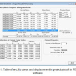 |
Figure1: Table of results stress and displacement in project aircraft in FEAFAA software Click here to View figure |
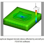 |
Figure2: Graphical diagram tensile stress affected by aircraft project wheel in FEAFAA software Click here to View figure |
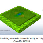 |
Figure3: Graphical diagram tensile stress affected by aircraft project wheel in ABAQUS software Click here to View figure |
After completing the analysis, the maximum tensile stress for loading aircraft wheel under concrete slab by FEAFAA and ABAQUS software was compared according to Table 4.
Table4: Results of the analysis of stress under concrete slab
| Percent of Differance | FEAFAA | ABAQUS | Airplane |
| Max.Tensile Stress (kpa) | Max.Tensile Stress (kpa) | ||
| 6.2 | 1301 | 1389 | A300-B4 std |
| 3.5 | 1215 | 1260 | B747-sp |
| 3.2 | 890 | 920 | FOKKER 100 |
According to the results obtained, it was found that the stress values in axis XX in both software’s closely associated, thus we will consider the maximum stresses by ABAQUS software as basis of our operation and obtain ratio of tensile stress for each aircraft relative aircraft based project. now, assuming the number of flight Average 1 for each aircraft and using the equivalent number of flight coefficient table, Other aircrafts relative to aircraft based project was obtained which is considered the aircraft FOKKER100 regarding to relations that was previously described according to Table 5.
Table5: Table number of flight equivalent aircraft based project
| Ratio of Tensile Stress | Flight number of equivalent Aircraft Based Project | Wheel Load (N) | Flight number of equivalent Axis Aircraft Project | Average fight | Airplane |
| 1.51 | 2 | 197200 | 1.70 | 1 | A300-B4 std |
| 1.37 | 2 | 189500 | 1.70 | 1 | B747-sp |
| 1 | 1 | 110000 | 1 | 1 | FOKKER 100 |
By calculating the number of flight equivalent aircraft project, it was found that each one flight A300-B4 std aircraft is equal to 2 flights FOKKER 100 And each flight aircraft B747-sp is equal to 2 FOKKER 100 aircraft.
Conclusion
The results show that the wider the wheel arrangement, the less stress resulting from load of aircraft. With this discussion we can say that there was no correlation between stress ratios among different aircrafts than together with the number of their flight. So that the ratio stress of concrete slab under load wheels of the B747-sp aircraft with FOKEER 100 was about 1.4, While the number of its equivalent flight is 2 times. Also ratio stress of A300-B4 std aircraft to FOKEER 100 is approximately equal to 1.5 and the number of its equivalent flight equals 2. On the other hand, according to Table 7 number of flight A300-B4 std aircraft and B747-sp on based aircraft project (FOKKER 100) is equal and this is while the amount of maximum tensile stress concrete slab in A300-B4 std aircraft is greater than B747-sp.
References
- Robert Horonjeff, Francis X. McKelvey, William J. Sproule and Seth B. Young. “ Planning and Design of Airports”,.pp 268-270 (2010).
- U.S. Department of Transportation, Federal Aviation Administration, Airport Pavement Design for the Boeing 777 Airplane, Advisory Circular 150/5320-16, (1995).
- Brill, D.R., “Development of Advanced Computational Models for Airport Pavement Design,” Final Report DOT/FAA/AR-97/47, U.S. Department of Transportation, Federal Aviation Administration, Office of Aviation Research, Washington, D.C. 20591, August (1998).
- Christon, M.A. and Dovey, D., “INGRID – A 3D Mesh Generator for Modeling Nonlinear Systems,” Report No. UCRL-MA-109790 (Draft), Lawrence Livermore National Laboratory, Livermore, California, September (1992).
- Maker, B.M., NIKE3D - An Nonlinear, Implicit, Three-Dimensional Finite Element Code for Solid and Structural Mechanics - User's Manual Report UCRL-MA-105268, Rev. 1, Livermore, California, Lawrence Livermore National Laboratory, (1995).
- Brill, D.R., “Field Verification of a 3D Finite Element Rigid Airport Pavement,” Final Report DOT/FAA/AR-00/33, U.S. Department of Transportation, Federal Aviation Administration, Office of Aviation Research, Washington, D.C. 20591, July (2000).
- Cook, R.D., Malkus, D.S., Plesha, M.E., Witt, R.J., Concepts and Applications of Finite Element Analysis (Fourth Edition), John Wiley & Sons, Inc., (2001).
- Hughes, T.J.R., The Finite Element Method, Dover Publications, Inc., New York, (2000).
- Huang, Y.H., Pavement Analysis and Design, Englewood Cliffs, NJ, Prentice-Hall, (1993).
- U.S. Department of Transportation, Federal Aviation Administration, Airport Pavement Design and Evaluation, Advisory Circular 150/5320-6D, (1995).
- Hammons, M.I. and Ioannides, A.M., Advanced Pavement Design: Finite Element Modeling for Rigid Pavement Joints, Report I - Background Investigation, Report No. DOT/FAA/AR-95/85, FAA (1997).
- Brill, D.R., Wang, Q., and Guo, E.H., “Finite Element Simulation of Surface Strain Gage Measurements in Rigid Airport Pavements,” in Proceedings of the 2nd European Airport Pavement Workshop 2009, CROW, May 12-14, (2009).
- Wang, Q., Chen, Y., “Improvements to the Modeling of Concrete Slab Curling Using the Finite Element Program NIKE3D”, in Proceedings of the Transportation Research Board (TRB) 90th Annual Meeting, January, Washington, D.C. (2011).